Voltametric Tests
In this section we describe pre-programmed tests defined the potentiostat shield’s firmware.
Cyclic voltammetry
In cyclic voltammetry current is measured while the potential (voltage) between the working and reference electrode is ramped up and down cyclically in piecewise linear fashion - in a triangle waveform - for a number of cycles. This triangle waveform can be specified by the amplitude, offset, period and (phase) shift in a manner similar to a sine wave. Prior to beginning the triangle waveform output, the test procedure waits for a (optional) quiet period during which the voltage is held as a user specified value. The quiet period is defined by the quietTime and quietValue parameters. Immediately following the end of the quiet period the triangle waveform output begins. The seven parameters used to define the cyclic voltammetry test are test are summarized in the table below.
parameter |
description |
units |
type |
|---|---|---|---|
quietValue |
output value during the quiet period |
V |
float |
quietTime |
duration of quiet period |
ms |
integer |
amplitude |
peak amplitude of triangle waveform |
V |
float |
offset |
offset of triangle waveform from zero |
V |
float |
period |
period of triangle waveform |
ms |
integer |
numCycles |
number of cycles to perform |
NA |
integer |
shift |
unitless phase shift for waveform |
NA |
float |
The parameters can be set in the Rodeostat’s firmware using the
set_param() method and are passed as a
dictionary. An example dictionary containing the parameters for the cyclic
voltammetry is shown below.
{
     'quietValue' : -0.1,   # quiet period voltage (V)
     'quietTime'  : 1000,   # quiet period duration (ms)
     'amplitude'  :  0.6,   # waveform peak amplitude (V)
     'offset'     :  0.5,   # waveform offset (V)
     'period'     : 2000,   # waveform period (ms)
     'numCycles'  :    2,   # number of cycles
     'shift'      :  0.0,   # unitless phase shift
 }
The following figure illustrates the output voltage of the potentiostat with these parameters.
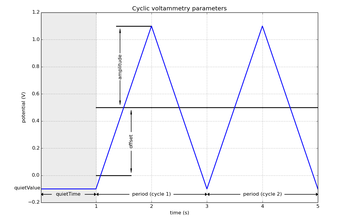
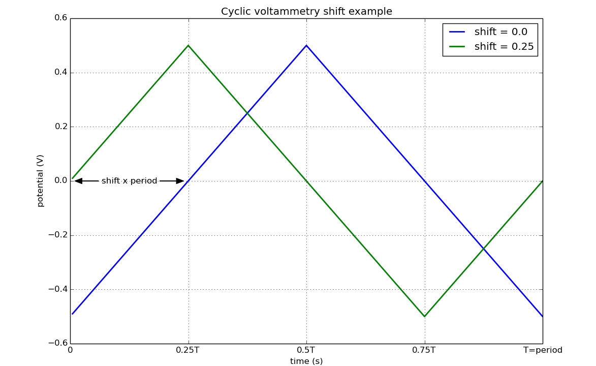
When the shift parameter is zero the triangle waveform output for the cyclic voltammetry test will start at the minimum value. This behaviour can be changed by entering a value for the shift parameter in the range [0,1]. The periodic triangle waveform will then be shifted forward (in time) by and amount equal to shift x period. Thus a shift value of 1/4 would shift the triangle waveform a quarter of a cycle forward, a shift value of 1/2 would shift the triangle waveform a half a cycle forward, etc. An example demonstrating the effect of the shift parameter is shown below.
Note
Sometimes the output waveform for cyclic voltammetry specified using the scan rate (V/s) and the maximum/minimum voltage values in the waveform. The relationship between these values and the amplitude, offset and period as are as follows:
scan rate = 4 x amplitude/period
maximum voltage = offset + amplitude
minimum voltage = offset - amplitude
or alternatively
amplitude = 0.5 x ( (maximum voltage) - (minimum voltage) )
offset = 0.5 x ( (maximum voltage) + (minimum voltage) )
period = 4 x amplitude / (scan rate)
where period has units of (s) and scan rate has units of (V/s)
More information on cyclic voltammetry can be found here https://en.wikipedia.org/wiki/Cyclic_voltammetry [1]
Linear sweep voltammetry
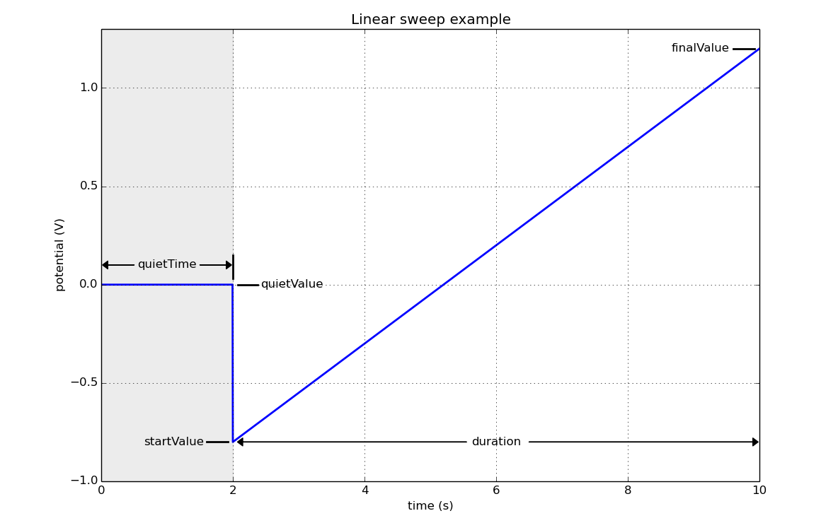
In linear sweep voltammetry current is measured while the potential between the working and reference electrode sweeps linearly over a some range. The range is specified by a starting value, startValue, a final value, finalValue, and a duration. Prior to beginning the linear sweep, the test procedure waits for a (optional) quiet period during which the voltage is held as a user specified value. The quiet period is specified by the quietTime and quietValue parameters. The five parameters used to define the linear sweep voltammetry test are test are summarized in the table below.
parameter |
description |
units |
type |
|---|---|---|---|
quietValue |
output value during the quiet period |
V |
float |
quietTime |
duration of quiet period |
ms |
integer |
startValue |
linear sweep starting value |
V |
float |
finalValue |
linear sweep final value |
V |
float |
duration |
linear sweep duration |
ms |
integer |
The parameters can be set in the Rodeostat’s firmware using the
set_param() method and are passed as a
dictionary. An example dictionary containing the five parameters for the
linear sweep voltammetry is shown below.
{
    'quietTime'  : 2000,   # quiet period voltage (V)
    'quietValue' :  0.0,   # quiet period duration (ms)
    'startValue' : -0.8,   # linear sweep starting value (V)
    'finalValue' :  1.2,   # linear sweep final value (V)
    'duration'   : 8000,   # linear sweep duration (ms)
}
The following figure illustrates the output voltage of the potentiostat with these parameters.
Note
The scan rate (V/s) can be found from the startValue, finalValue and duration as follows:
scan rate = abs(finalValue - startValue)/duration
where duration has units of (s).
Additional information on linear sweep voltammetry can be found here https://en.wikipedia.org/wiki/Linear_sweep_voltammetry [2]
Constant voltage
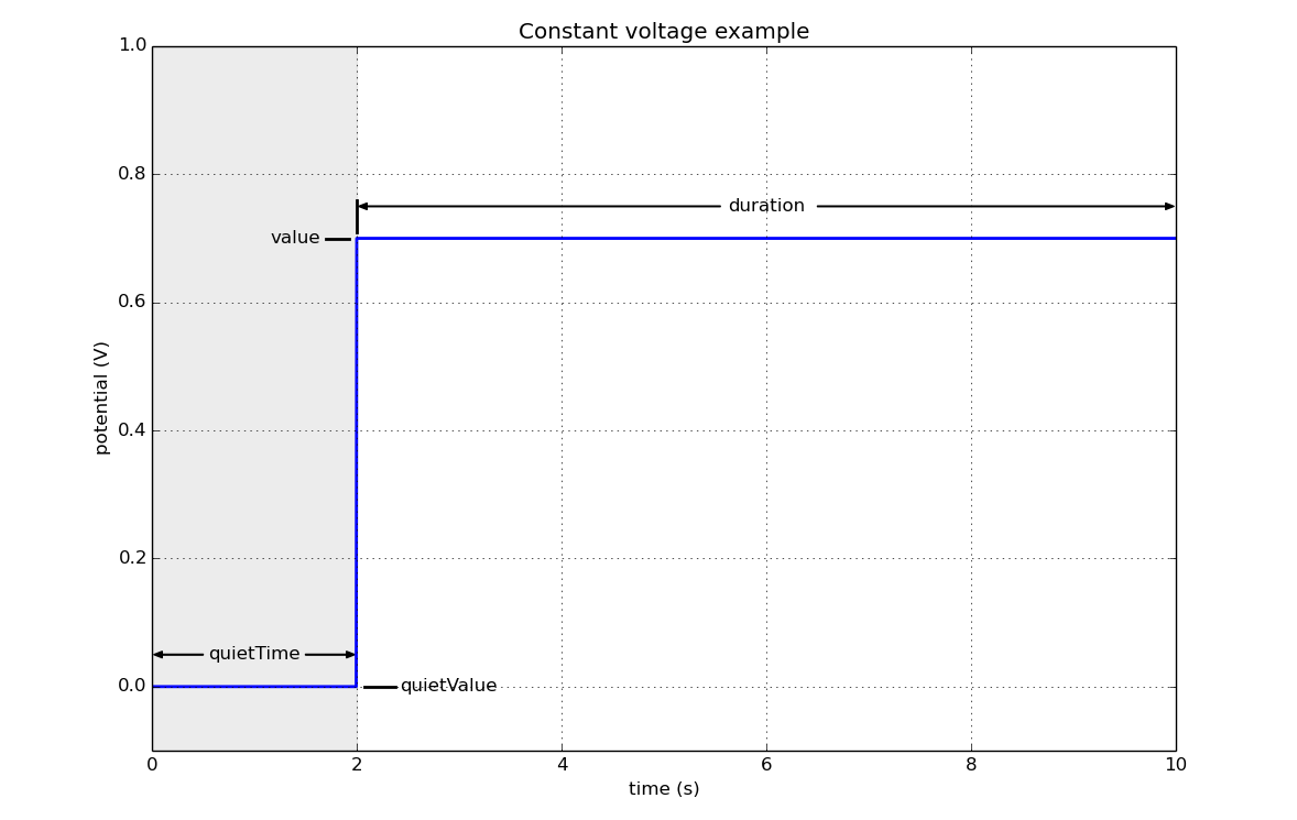
The constant voltage test measures the current while the potential between the working and reference electrode is held constant. Like the other tests the constant voltage test includes an optional quiet period where the output voltage is held and constant value (quietValue) for a fixed duration (quietTime) prior to the start of the test. The four parameters which specify the voltage output for the constant voltage test are summarized in the table below.
parameter |
description |
units |
type |
|---|---|---|---|
quietValue |
output value during the quiet period |
V |
float |
quietTime |
duration of quiet period |
ms |
integer |
value |
output value during the test period |
V |
float |
duration |
duration of the test period |
ms |
integer |
The parameters can be set in the Rodeostat’s firmware using the
set_param() method and are passed as a
dictionary. An example dictionary containing the four parameters for the
constant voltage test is shown below.
{
    'quietValue' : 0.0,
    'quietTime'  : 2000,
    'value'      : 0.7,
    'duration'   : 8000,
}
The following figure illustrates the output voltage of the potentiostat with these parameters.
Sinusoidal voltammetry
parameter |
description |
units |
type |
|---|---|---|---|
quietValue |
output value during the quiet period |
V |
float |
quietTime |
duration of quiet period |
ms |
integer |
amplitude |
peak amplitude of sinusoid waveform |
V |
float |
offset |
offset of sinusoid waveform from zero |
V |
float |
period |
period of sinusoid waveform |
ms |
integer |
numCycles |
number of cycles to perform |
NA |
integer |
shift |
unitless phase shift for waveform |
NA |
float |
{
    'quietValue' : 0.0,
    'quietTime'  : 0,
    'amplitude'  : 2.0,
    'offset'     : 0.0,
    'period'     : 2000,
    'numCycles'  : 3,
    'shift'      : 0.0,
}
Square wave voltammetry
parameter |
description |
units |
type |
|---|---|---|---|
quietValue |
output value during the quiet period |
V |
float |
quietTime |
duration of quiet period |
ms |
integer |
amplitude |
amplitude of square wave |
V |
float |
startValue |
start voltage for staircase |
V |
float |
finalValue |
final voltage for staircase |
V |
float |
stepValue |
step voltage for stair case |
V |
float |
window |
[0,1] value size of averaging window |
NA |
float |
The output waveform is the sum of a staircase and a square wave.
The period of the square wave is 1.0/sample_rate.
The window parameter, a unitless number in [0,1], sets the size of the averaging window used for sampling at the end of each half cycle. The value specifies the fraction of the half cycle used - starting from the end.
{
    'quietValue' : -0.6,
    'qietTime'   : 1000,
    'startValue' : -0.6
    'finalValue' : 0.4,
    'stepValue'  : 0.005,
    'amplitde'   : 0.05,
    'window'     : 0.2,
}
Chronoamperometry
parameter |
description |
units |
type |
|---|---|---|---|
quietValue |
output value during the quiet period |
V |
float |
quietTime |
duration of quiet period |
ms |
integer |
step |
list (len=2) of (duration,value) tuples |
(ms, V) |
(integer, float) |
{
    'quietValue' : 0.0,
    'quietTime'  : 1000,
    'step'       : [(1000,-0.25), (1000,0.5)],
}
Multistep voltammetry
parameter |
description |
units |
type |
|---|---|---|---|
quietValue |
output value during the quiet period |
V |
float |
quietTime |
duration of quiet period |
ms |
integer |
step |
list (len=<50) of (duration,value) tuples |
(ms, V) |
(integer, float) |
{
    'quietValue' : 0.0,
    'quietTime'  : 1000,
    'step'       : [(1000,-0.5), (1000,-0.2), (1000,-0.3), (1000,-0.0), (1000,-0.1), (1000,0.3), (1000,0.2), (1000, 0.5)],
}
Squarewave voltammetry
parameter |
description |
units |
type |
|---|---|---|---|
quietValue |
output value during the quiet period |
V |
float |
quietTime |
duration of quiet period |
ms |
integer |
amplitude |
amplitude of the squarewave |
V |
float |
startValue |
starting value of linear sweep |
V |
float |
finalValue |
final value of linear sweep |
V |
float |
stepValue |
step in voltage for each cycle |
V |
float |
window |
fraction of half cycle used for sample |
NA |
float |
{
    'quietValue' : -0.4,
    'quietTime'  :  500,
    'amplitude'  :  0.05,
    'startValue' : -0.4,
    'finalValue' :  0.2,
    'stepValue'  :  0.005,
    'window'     :  0.2,
}